

In recent years, quadcopter drones have become a popular remote-controlled unmanned aerial vehicle (UAV) model, and many beginners are interested in trying out the joy of remote-controlled flight by building one themselves. However, buying a ready-to-fly quadcopter can be expensive and may not provide a comprehensive understanding of the various features and highlights of this emerging model. Many hobbyists who are new to quadcopter drones or come from other aircraft models may wonder how to DIY a quadcopter drone themselves. The following DIY tutorial for a quadcopter drone is very practical and has a low cost, as the aircraft body can be completed for only 6 dollar and a weekend. So what are you waiting for? Let's make a quadcopter drone together!
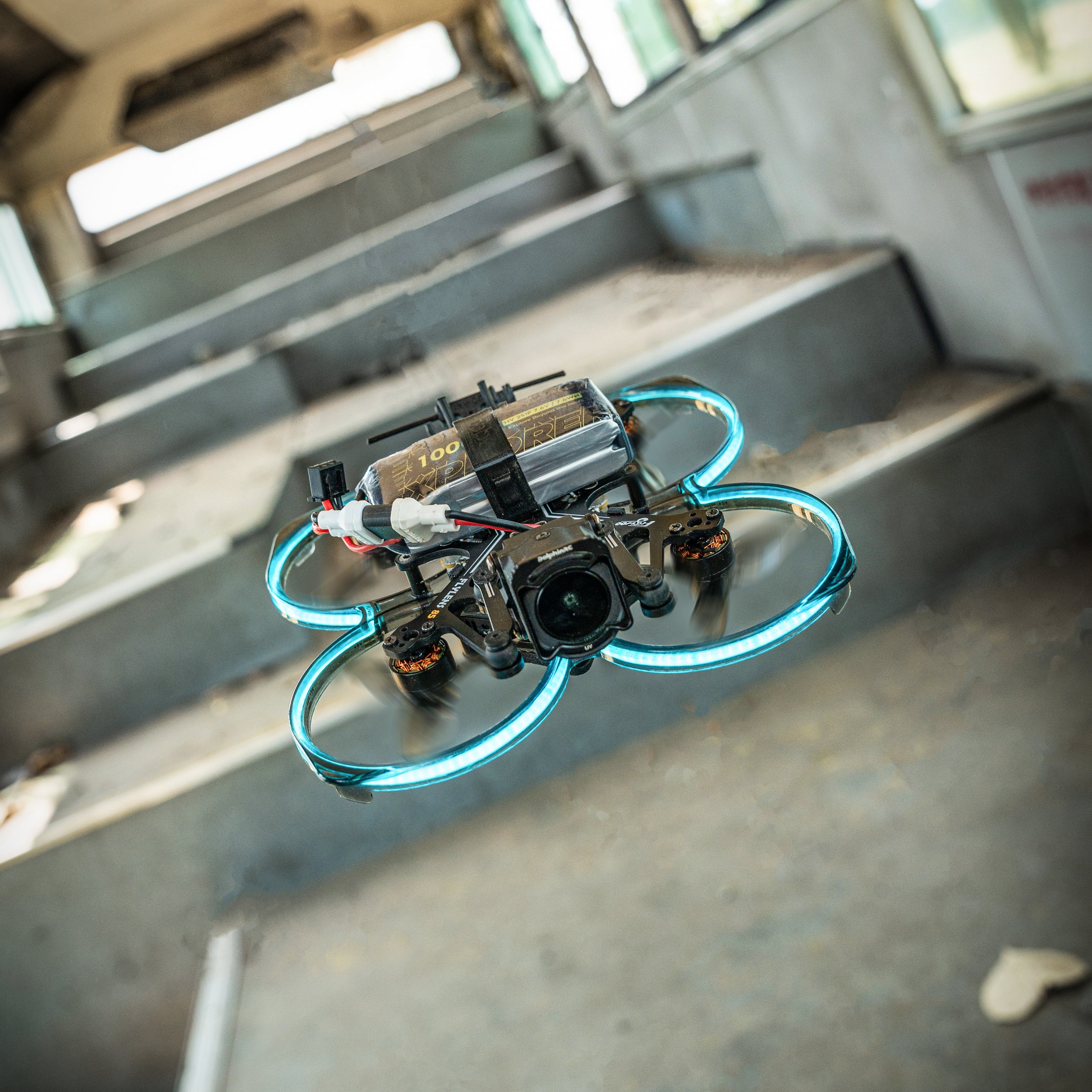
Quadcopter Structure for Aerial Photography

-
Frame: The skeleton of the aircraft that carries various equipment.
-
Flight controller: The "brain" of the aircraft that carries sensors such as accelerometers, gyroscopes, barometers, and compasses. It controls the speed of the four motors to control the attitude of the aircraft. With GPS, it can also perform functions such as maintaining altitude and returning to home position. Its essence is a microcontroller. Common flight controllers include Xaircraft's SuperX, DJI's Naza WKM A2, Zero's X4 Gemini, APM, MWC, QQ flight controller, CC3D, etc.
-
Electronic Speed Controller (ESC): It takes in DC power, usually supplied by 2-6 lithium batteries, and outputs three-phase AC to directly drive the motor. In addition, brushless ESCs for model aircraft have three signal output wires for connecting to the receiver. The signal wire can provide a stable 5V voltage and can power 2-4 servos. Model aircraft adjust various flight attitudes and actions by controlling the brushless ESC through remote control.
-
Brushless motor: It generates a rotating magnetic field through three-phase AC to drive the rotor to rotate. It features wide speed control, small size, high efficiency, and small steady-state speed error. The KV value of the brushless motor is defined as the ratio of speed to voltage, meaning that with an increase of 1 volt in input voltage, the no-load speed of the brushless motor will increase by a certain speed value. However, the relationship between the speed of the brushless motor and the voltage is not strictly linear.
-
Remote control and receiver: As the name suggests, it is used to receive and send commands.
DIY Aerial Vehicle Tool Basics

To minimize unnecessary expenses, it is recommended to purchase the following tools and supplies in one go:
soldering iron, wire stripper, lead cutter (regular pliers cannot grip thick silicone wire), set of hex keys, set of screwdrivers, small pliers, components, spirit level, heat shrink tubing (4mm and 5mm are used more frequently, others depend on the situation), buzzer (buy a few spares as they are easy to lose)
DIY tutorial for aerial drones
Step 1: Building the body
The center hub of a quadcopter is made up of two pieces of PCB board. Download the template for cutting and drilling here, output it to the actual size, and temporarily stick it to the PCB board. Use a plastic carving knife to make marks, and then use a 1/8" drill bit to drill holes.
Step 2: Cut the brackets and drill holes
Cut four 10"-11" square wooden brackets. The shorter the arms, the more agile the drone, but the longer the arms, the more stable the drone. Drill two small 3mm holes in each bracket, one 6mm from the tail end and the other 26mm from the tail end.
Step 3: Assemble the body
Fasten the brackets to the PCB board with screws. Use an M3×25mm screw to secure the inner hole, and an M3×20mm screw to secure the outer hole. Once the brackets are secured with screws and look good, apply screw sealant to the outer hole screws, put on and tighten the nuts; gently screw on the nuts for the inner hole screws, no need to tighten.
Step 4: Connect the power core
The power core consists of six parts: four electronic speed controllers, a power module, and a camera stabilizer control board. First, separate the XT60 connector and APM power module line. Strip about 1/4" of insulation from each red and black wire, and tin the ends of the stripped wires. Cut off 3/8" rings from each end of a copper shrink tube, file down any rough edges, solder the positive terminals of the six red wires to the inner ring, and connect the corresponding six negative terminals to the outer ring. Wrap the inner ring with foam waterproof tape and cover it with the outer ring. Finally, apply insulation glue to the entire center.
Connecting the motors and electronic speed controllers can be a tedious job. Buying a power distribution board directly would be easier, but it would take up space and add weight. I prefer to make my own power distribution board using the two rings of a shrink copper tube, which looks very precise and neat.

Step 5: Drilling the Motor Mounting Base
Here we teach you how to easily make landing gear using a common C-shaped clamp. You can also buy cheap combination landing gear/motor mounts to simplify the manufacturing process.
If you plan to make the landing gear yourself, you will need to mount the motor directly on the gear. First, mark each gear leg and drill a small, inconspicuous blind hole to allow the motor shaft to rotate freely. A 5/16" drill bit is a good choice.
Step 6: Installing the Motor
Cut the motor mount, and use two M3x20mm screws to secure the motor and mount to the tail end of the quadcopter frame. You must tighten each screw, and make sure the motor shaft can rotate freely. If it does not rotate freely, check the quadcopter frame grooves again, and finally file the edges of the motor mount smooth.
Step 7: Adding the Landing Gear
Slide the power core between the two transparent plates, and wrap the power cables of the electronic speed controller around the four landing gear legs. If the motor and electronic speed controller are made by the same manufacturer, there may be pre-installed "bullet" connectors. In this case, simply plug the motor wires into the speed controller wires, and wind any excess wire around the bottom of the gear legs. You can also solder the wires directly to the electronic speed controller control board to simplify the structure. Secure the motor wires and electronic speed controller wires with cable ties, and tie up any excess wire under the gear legs.
Cut the four C-shaped clamps in half with wire cutters, set the J-shaped base aside, file the cut surface smooth, and then grind two small grooves on both sides of the mounting hole. Mount this base at the tail end of each gear leg, inside the motor frame, and wrap the cable tie around the grooves just filed.
Step 8: Installing the Shock Absorption Pads
Remove the PVC hose clamps and save them for other topics. Use a pen-style craft knife to cut two 3/4" plastic rings from the rubber hose, and press them with your thumb to form two dents on the screw protruding from the frame. Then, drill a hole in each dent with a 1/8" drill bit, but do not drill through to the other side. Use M3 flat washers and nuts to lock the plastic rings on the frame, adjust the tightness, and fix them with screw sealant.
Cut two shock absorption pads from the hose to install the gimbal and battery holder, to prevent the camera from being affected by the propeller vibration. Also make some space above for installing the gimbal controller.
Step 9: Installing the Camera and Battery Holder
The panoramic mount and battery holder can be assembled from three sets of individual L-shaped brackets. I call them the bracket, roll axis, and pitch axis brackets.
Cut the aluminum rod (1/8" x 3/4" x 36") into two 18" aluminum strips, and cut one of them into a 9" strip, for a total of three aluminum strips. Fold each strip into a right angle, and use a wood or aluminum block with a beveled edge to increase the bending radius to 3/8" (excessive bending may damage the support of the aluminum strip). After the aluminum strip is bent, drill four 1/8" holes at the ends of the bracket, and drill two 1/8" holes in the middle of the roll axis and pitch axis brackets. Finally, assemble the panoramic mount and battery holder using screws and nuts.


Leave a comment